Announcement

Collapse
No announcement yet.

Can not understand this wiring!!

Collapse

Forum Top GA Ad Widget

Collapse
X
 
  • Filter
  • Time
  • Show
Clear All
new posts

  • Can not understand this wiring!!

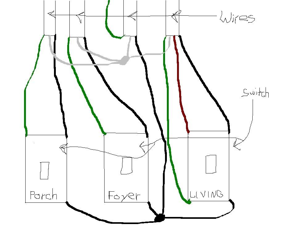
    Here goes. Inside my front door I have 3 switches. 1 for the porch light, 1 for the foyer light and 1 for the living room. The living room is also controlled by another switch. They all work fine. I put a lamp module in the porch light so that it can be controlled by a motion sensor and a hand keld key fob. Now the only way the the sensor or the fob will turn on the light is if the living room light is off. I can use the fob to turn on the light while the living room light is out and then turn the living room light on and the porch light stays but can be no longer cotrolled by the sensor or the fob. The foyer light is fine. What can be the problem. Here is a little diagram of the electrical switch box. Thanks for your help in advance.

    Jtfoxman

  • #2
    OK, diagram looks fine - the load for the living room will be taken off the three way switch at the remote end. the first switch has the porch, the second has the foyer and the third is the LR. My question to you is do the instructions say that you must have power ON at all times to the motion/ controlled lamp? Reason I say this is because most motion sensors or photocells need a constant 120 volts for the electronics to work, otherwise every time you turn the power on, they go through a self check, turn on then go off.

    Comment


    • #3
      Yes, it needs power all the time. And it does get power because I can turn the light on with the fob while the living room light is off and then turn the living room light on and the power stays on to the porch but the fob will not work.

      The light works fine without the motion sensor installed.
      Jtfoxman

      Comment


      • #4
        ok, then keep the switch on all the time for the porch light [the in-wall toggle]. why the three ways would have an effect on the wireless remote is beyond me.

        Comment


        • #5
          I do keep the light on at all times but that switch still affects it.

          The wiring is ok though, correct?
          Jtfoxman

          Comment


          • #6
            I can't believe it. I have the low voltage flourescent bulbs in the living room light. I chenged them back to regular bulbs and everything now works fine.

            Would you have any idea why? Does it have something to do with haw much current it draws. Right now I have 3 60 watt candlebra bulbs and it works fine. Before I had 4 flourescent 4w bulbs and it did not work.

            I compromised and placed 2 60w in and 3 4w flourescents. Will mixing them cause any problems and is it safe?
            Last edited by jtfoxman; 02-21-2009, 01:57 PM. Reason: Adding something
            Jtfoxman

            Comment


            • #7
              you didn't say that before so I assumed regular bulbs. low voltage flourescents are `12 volt DC - never seen low volts type AC. problems? try it and see.

              Comment


              • #8
                Sorry for the confusion. There not fluorescent there just the cfl energy bulbs in a ceiling fan. I changed them back to incandescent bulbs and everythinh works. Now I have 3 cfl's in the fan and 2 regular bulbs that are not even screwed in all the way and it works. Very weird.
                Last edited by jtfoxman; 02-21-2009, 07:19 PM. Reason: spelling
                Jtfoxman

                Comment


                • #9
                  The CFL's will not work properly, possibly not at all, off control devices like motion sensors.


                  Disregarding that problem, you seem to have a proper set up. If it is wired as shown, all three switches have hot feeds all the time. The setting of the living room switch should not affect the porch circuit, unless that 3 way switch is in wrong. There should be one identified screw, probaly painted black, and that hot power lead should be connected to that one.

                  Comment


                  • #10
                    Originally posted by HayZee518 View Post
                    OK, diagram looks fine...
                    Only if you're looking at the hots. Look again at the grounds.

                    The ground wire from the supply cable is folded back (and apparently not connected to anything) and the other ground wires only run from the individual switches to their respective loads - meaning that all 4 switches (counting the other 3-way) and all 3 loads are not grounded. The ground wires from all cables need to be connected to the supply ground, along with pigtails to the switches. If the box is metal, it must also be connected to the supply ground.

                    Whoever folded back the supply ground and yet still connected the other greens to the switches had no idea what they were doing.

                    Comment


                    • #11
                      that slipped by me - all grounds have to be connected together and like HE said if metal boxes are used, and ganged together bonded to the box.

                      Comment

                      Working...
                      X
                      =