
 Tweet
Tweet
There's more:
Click, click, click. Your Monitor heater has a solenoid pump, about the size of a marking pen, that operates quietly when fuel is present at the fuel sump. If your tank ran out, or there are air pockets in the supply line, then you will hear the fuel pump click, click, click. That is the sound of a fuel pump without fuel. The red button reset (not a primer) at the lower right side of your Monitor heater releases a magnetic valve that may be stopping your fuel. If so, you will hear the click click go to clunk clunk and thump thump as fuel reaches the pump. If air in the line prevents fuel reaching the heater, it will need to be bled from the line to bring a steady fuel supply to the heater. This is not a heater problem. It is a fuel supply problem.
Heater won’t start. Is it plugged in? Does the indicator light illuminate? Do your hear the hum of the combustion fan, but nothing else happens? Find the air switch. It is cookie size, stands on edge near the front of the same compartment as the Constant Level sump. The air switch has a micro switch with two wires attached. When this switch closes, it tells the control board all is well (the combustion fan is bringing air into the combustion chamber). What activates this switch is the rubber air hose attached to the cookie size air diaphragm. Occasionally, this diaphragm fails, but more often it stops working because the rubber air hose is split, right at the end attached to the air switch assembly. This split rubber hose will prevent the heater from starting the burn. You could go to the trouble of ordering Monitor part number XXXX, but why bother? I use 3/32”automotive vacuum hose, from the auto parts store. Quicker, cheaper, lasts longer. Clear silicone tubing is NOT recommended.
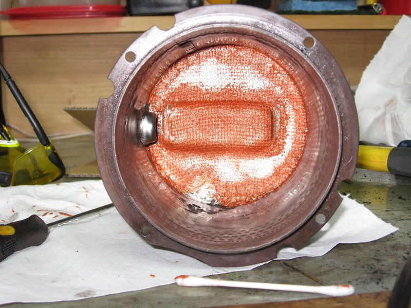
Starts up, shuts down. Does the fuel come to the heater, but is blocked from the combustion chamber? It is easy to check. Where the small copper fuel line enters the combustion chamber, it may be inspected. Use a 13 mm open end wrench, or small adjustable wrench, disconnect the line from the combustion chamber. The line pulls out, and so do the washer and rubber spacer; don’t lose them. The fuel line itself does not clog, but carbon may build up on the tube that goes into the chamber, partially blocking fuel from getting to where it needs to be. If this is the case, the symptom will be start up and shut down, with an error code of flame failure. Essentially, it ran out of fuel. A drill bit may be too short, but a piece of bailing wire 3 inches long (I use a bicycle spoke) will be enough to push carbon out of the way at the far end of the fuel inlet. If carbon is blocking the inlet, you will feel it as it pushes out of the way. If there is no resistance at all, there was no blockage. While this is not the condition with every heater that stops, it is easy to check, and it is easy to overlook. Put it back together, and move on to the next common problem.
Flame failure. The flame rod is telling the control board to shut down the heater. Why?
The flame rod has a job to do, and while it is not a union job, it requires very specific working conditions. When the heater is operating, you may be able to look into the inspection window, down and to the right. To see it in its working position when the heater is not operating (and cool), remove the window base panel (10 screws, the panel 4 by 7 inches on the front of the combustion chamber. If the gasket goes to pieces, replace it with Monitor part number 6850, about $16). The flame rod is to the right and below the opening. Use a flashlight to see where it is, between the burn chamber wall and the burn ring. In this half inch opening, it should be centered. If there is carbon build up (a carbon bridge) from the rod to either side, the heater will shut down. If the burn ring is very near the rod, it may touch it as the heater warms up, and the heater will shut down.
How does the flame rod work? It conducts electrical current through the flame itself to the board, telling the control circuit the flame is present and all is well. If the rod shorts out by carbon, or by touching the metal on either side, the signal to the control circuit is that all is not well, and the board responds by shutting the heater down. The burn ring, or combustion ring, looks like a cereal bowl upside down in the middle of the heater. It is stainless steel, and glows red hot in heater operation. New, it starts out perfectly round, but may warp over time. If the warp is wide at the flame rod position, and touches the rod, that condition can shut down the heater.
@@@
Proceed to Level Two?
jimmyj55.com is restocking Monitor parts for the season, for all those who insist (by intent or by desperation) on repairing their own heaters.
Click, click, click. Your Monitor heater has a solenoid pump, about the size of a marking pen, that operates quietly when fuel is present at the fuel sump. If your tank ran out, or there are air pockets in the supply line, then you will hear the fuel pump click, click, click. That is the sound of a fuel pump without fuel. The red button reset (not a primer) at the lower right side of your Monitor heater releases a magnetic valve that may be stopping your fuel. If so, you will hear the click click go to clunk clunk and thump thump as fuel reaches the pump. If air in the line prevents fuel reaching the heater, it will need to be bled from the line to bring a steady fuel supply to the heater. This is not a heater problem. It is a fuel supply problem.
Heater won’t start. Is it plugged in? Does the indicator light illuminate? Do your hear the hum of the combustion fan, but nothing else happens? Find the air switch. It is cookie size, stands on edge near the front of the same compartment as the Constant Level sump. The air switch has a micro switch with two wires attached. When this switch closes, it tells the control board all is well (the combustion fan is bringing air into the combustion chamber). What activates this switch is the rubber air hose attached to the cookie size air diaphragm. Occasionally, this diaphragm fails, but more often it stops working because the rubber air hose is split, right at the end attached to the air switch assembly. This split rubber hose will prevent the heater from starting the burn. You could go to the trouble of ordering Monitor part number XXXX, but why bother? I use 3/32”automotive vacuum hose, from the auto parts store. Quicker, cheaper, lasts longer. Clear silicone tubing is NOT recommended.
Starts up, shuts down. Does the fuel come to the heater, but is blocked from the combustion chamber? It is easy to check. Where the small copper fuel line enters the combustion chamber, it may be inspected. Use a 13 mm open end wrench, or small adjustable wrench, disconnect the line from the combustion chamber. The line pulls out, and so do the washer and rubber spacer; don’t lose them. The fuel line itself does not clog, but carbon may build up on the tube that goes into the chamber, partially blocking fuel from getting to where it needs to be. If this is the case, the symptom will be start up and shut down, with an error code of flame failure. Essentially, it ran out of fuel. A drill bit may be too short, but a piece of bailing wire 3 inches long (I use a bicycle spoke) will be enough to push carbon out of the way at the far end of the fuel inlet. If carbon is blocking the inlet, you will feel it as it pushes out of the way. If there is no resistance at all, there was no blockage. While this is not the condition with every heater that stops, it is easy to check, and it is easy to overlook. Put it back together, and move on to the next common problem.
Flame failure. The flame rod is telling the control board to shut down the heater. Why?
The flame rod has a job to do, and while it is not a union job, it requires very specific working conditions. When the heater is operating, you may be able to look into the inspection window, down and to the right. To see it in its working position when the heater is not operating (and cool), remove the window base panel (10 screws, the panel 4 by 7 inches on the front of the combustion chamber. If the gasket goes to pieces, replace it with Monitor part number 6850, about $16). The flame rod is to the right and below the opening. Use a flashlight to see where it is, between the burn chamber wall and the burn ring. In this half inch opening, it should be centered. If there is carbon build up (a carbon bridge) from the rod to either side, the heater will shut down. If the burn ring is very near the rod, it may touch it as the heater warms up, and the heater will shut down.
How does the flame rod work? It conducts electrical current through the flame itself to the board, telling the control circuit the flame is present and all is well. If the rod shorts out by carbon, or by touching the metal on either side, the signal to the control circuit is that all is not well, and the board responds by shutting the heater down. The burn ring, or combustion ring, looks like a cereal bowl upside down in the middle of the heater. It is stainless steel, and glows red hot in heater operation. New, it starts out perfectly round, but may warp over time. If the warp is wide at the flame rod position, and touches the rod, that condition can shut down the heater.
@@@
Proceed to Level Two?
jimmyj55.com is restocking Monitor parts for the season, for all those who insist (by intent or by desperation) on repairing their own heaters.


Comment